A method for processing metals, metal alloys and metal matrix composite materials in a plastic injection molding machine is disclosed. The method includes the step of providing a plastic injection molding machine with a screw. The method includes the step of removing the screw. It also includes the step of replacing the screw with an improved screw that is configured and arranged for processing metal. Alternatively, it may include the step of removing the threads from the middle portion of the original screw shaft.
Summary of the invention
The improved screw for the Injection Molding Screw Barrel solves the problems of the prior art by providing a screw shaft that can be used to process metal in the injection molding machine. The screw has a shank, and the screw shaft extends from the shank. The screw shaft includes a front part, a middle part and a rear part. The screw shaft also includes multiple threads for advancing the material through the injection molding machine. In a preferred embodiment, the threads on the screw shaft extend only through the rear of the screw shaft. In an alternative embodiment, the thread may also be included in the front of the screw shaft.
Instead of manufacturing a new screw, the improved screw of the present invention can be made from a conventional plastic injection molded screw by selectively removing the middle and/or front threads of the screw shaft.
Screws can be used in traditional injection molding machines, traditionally used to process plastics to process metals.
Brief description of the drawings
These and other features, aspects and advantages of the present invention will be better understood with reference to the following description, appended claims and drawings, in which:
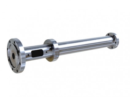
As shown in the figure. BRIEF DESCRIPTION OF THE DRAWINGS FIG. 1 is a plan view of a preferred embodiment of the screw design of the present invention;
As shown in the figure. Figure 2 is a partial cross-sectional view of a conventional plastic injection molding machine incorporating a preferred embodiment of the screw design of the present invention.
As shown in the figure. Figure 3 is a plan view of an alternative embodiment of the screw design of the present invention.
Detailed description of the preferred embodiment
Now refer to the figure. 1, the screw used in the injection molding machine of the present invention is generally disclosed as 10. The screw has a rod portion 12 from which a screw shaft 14 extends. The screw shaft 14 includes a front part 16, a middle part 18 and a rear part 20. The screw shaft 14 also includes a plurality of threads 22 for advancing the material through the injection molding machine. In a preferred embodiment, the threads 22 on the screw shaft 14 extend only through the rear portion 20 of the screw shaft 14. In an alternative embodiment 100, it is best to see Figure 1. As shown in FIG. 3, the thread 22 may also be included on the front portion 16 of the screw shaft 14. However, the thread 22 in the middle portion 18 of the threaded shaft 14 must be eliminated (or not included).
Now refer to the figure. In FIG. 2, the plastic injection molding machine equipped with the screw 10 of the present invention is generally shown at 24. The injection molding machine 24 includes a barrel portion 26, which is roughly divided into three areas: feeding, transition, and metering, which will be further explained as described below. The screw 10 is rotated by the motor 28 and inserted into the barrel. The material K is fed into the feeding area of the barrel 26 through the hopper 30 and the feeding throat 32. In the metering area of the barrel 26 is a nozzle 34 which is connected to a mold press 36 with a mold 38 having a cavity 40 and a sprue 42. The sprue 42 and the cavity 40 are in fluid connection with the nozzle 34. The temperature in the barrel 26 is partially controlled by the heater 44.
The screw 10 of the present invention allows a wide range of metals and their alloys and composite materials to be processed into 3D net shape parts using conventional injection molding equipment designed to process plastics. Although it is expected that traditional injection molding equipment cannot process all metals and their alloys according to temperature restrictions (such as high temperature steel, etc.), it is expected to find a series of alloys and their composites with commercial significance if they can use the installed global injection molding machine base For processing, the use will be more extensive.
The three main issues (ie, temperature capacity, mechanical capacity, and viscosity characteristics) have always been a major limitation for processing metals, metal alloys and their composites in traditional molding equipment. They are 1) viscosity control, 2) machine temperature and 3) machine mechanics.
Viscosity considerations are based on the fact that most metals and alloys have very low viscosity above their solidus temperature, especially above their liquidus temperature. It is difficult to control the flow of very low-viscosity fluids through the injection process and filling the cavity during the injection molding process. A high-viscosity melt with plastic flow as a function of temperature is produced, as mentioned in the previous publication.
The second problem is temperature, because the melting temperature of many useful metals and their alloys is higher than the standard range of traditional injection molding equipment. The typical range is 100-400°C (~200-800°F), because this range applies to almost all organic polymers, and generally, temperatures above 400°C (~800°F) tend to degrade any Organic compounds include polymers. The typical range available in commercial injection molding equipment is not higher than this value, simply because of lack of demand and higher additional costs. Nevertheless, there are still fairly simple modifications that will allow most standard Injection Molding Screw Barrels to operate at significantly higher temperatures (for example, up to 675°C/~1250°F). The heat input must be increased, which can be easily achieved by using a heating belt with a higher temperature and a higher rated power output. The machine construction is usually a specific steel grade with a fairly high temperature capability (usually well beyond the range of interest in this disclosure, which is as high as 675°C/~1250°F or approximately the melting point of pure aluminum). Other machine precautions, such as seals and auxiliary parts exposed to higher temperatures than normal due to the high temperature of the melting process, must also be taken into account, replaced more frequently, or replaced with higher temperature structural materials. Nonetheless, there are few obstacles to operating conventional injection molding equipment at significantly higher temperatures.
The third and most important consideration is the mechanical capabilities of the traditional Single Screw Extruder Screw Barrel. Historical attempts to process metals, metal alloys and their composite materials in traditional injection molding equipment have not been successful. This leads to serious unacceptable events, including barrel rupture, screw bending, motor damage and/or hot molten metal leakage/splashing. These events are mainly due to the machine's inability to overcome the strength of solid metal (or solidified metal, that is, crystal formation). Machine motors and/or structural materials often do not have enough capacity to overcome the strength, stiffness, and hardness characteristics of metals, so they fail first (for example, a broken barrel).
A good example of trying to overcome these phenomena is the so-called magnesium alloy thixoforming process. In this kind of special equipment, the size of the machine is very large compared with traditional injection equipment of similar tonnage (ie clamping force). The thixoforming machine may appear to be 50% larger in size than a conventional Single Screw Extruder Screw Barrel with similar clamping force, partly because of the additional torque and strength of the machine design required to process magnesium alloys. The thixoforming machine is designed to mechanically decompose/decompose in magnesium alloys (and most metals) when magnesium alloys (and most metals) are cooled or kept between their liquidus and solidus temperatures Microcrystals/crystals (dendrites) formed. Mechanically decomposing/decomposing crystals so that they can flow in a semi-solid medium is the design goal of a thixotropic process or machinery. For this and other reasons (such as the flammability of hot magnesium), specialized and more expensive equipment is required.
https://www.screwbarrel.co/screw-barrel-for-injection-machines/screw-barrel-for-injection-molding.html